This tutorial requires at least Blender 2.49b is installed.
Furthermore you need an object of your choice you like to create for Rule the Rail.
Appropriate objects for bezier curves are rounded objects such as any kind of locomotives.
For exactly recreating the shape of the object I strongly recommend a blueprint or
technical drawing which is true to scale and shows at least two sides of the object.
Photos are not as good as technical drawings and can only be used as templates for the texturing.
Visit The-Blueprints.com to find a proper blueprint
of your favorite locomotive, truck, car or whatever. You can also look for your desired object by searching directly for the name
using a search engine. Often you'll find a site with useful information such as the exact measurements and technical drawings.
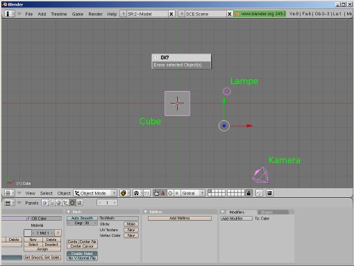
Start Blender and press a to select everything of the default scene. Press x or Del to delete all. Now the new model can be the only part of the scene without the default cube, camera and light. (The camera and the light is only needed within Blender for rendering and useless for the model when used in Rule the Rail)
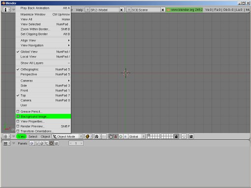
Now the technical drawing will be loaded as the background image for the scene. View > Background Image. Click Use Background Image in the following dialogue. Then click Load and select an image file. The setting Size will change the size of the image and with Blend the value for transparency can be changed.
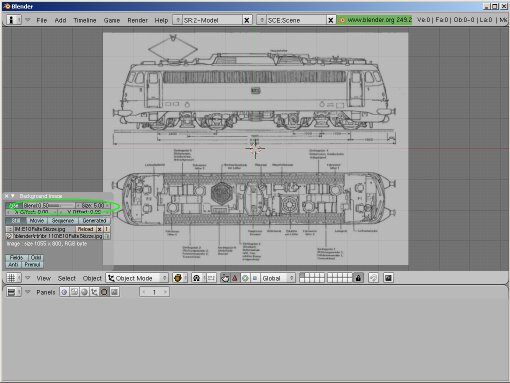
Adjust the image size. The engine has an overall length of 16440 mm (16,44 m). Inside Blender it will be about 16.440 units. (Before the dot 16 meter and after the dot 4 decimeter, 4 centimeter and 0 millimeter) Problems regarding the model size during im- / exporting to / from Rule the Rail often caused by wrong pre- / post-decimal position.
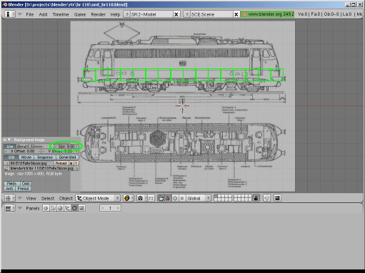
Now Size is exactly adjusted so the engine occupies 16 boxes on the grid. 1 box (Blender unit) = 1 meter.
(Or 1 yard if you prefer imperial measurement, simply use a different scale factor inside your .xli)
This should be enough so far.
The knowledge needed to continue is already published at:
Creating a Logo
Please take a look at the Creating a Logo tutorial before you continue.
Under User Preferences Edit Mehods activate Aligned to View! Press Num 3 to enter the side view and zoom in with the mousewheel. Press Strg+Num 2, Strg+Num 4, Strg+Num 6 or Strg+Num 8, and center the view.
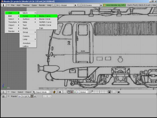
Spacebar, to add a bezier curve. Align the curve to the front shape. The example to the left uses three curves.
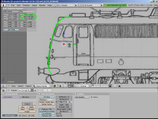
Change with Num 7 to the top view and move the view until it is centered. Spacebar, to add a bezier curve and align the shape to the half. Die Kontur nur bis zur Hälfte anpassen.
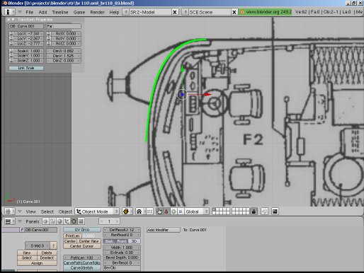
After the spadework is finished, the two curves can be aligned. Num 5, to switch the view from orthographic to perspective and align with Alt+LMB inside the 3D viewport.
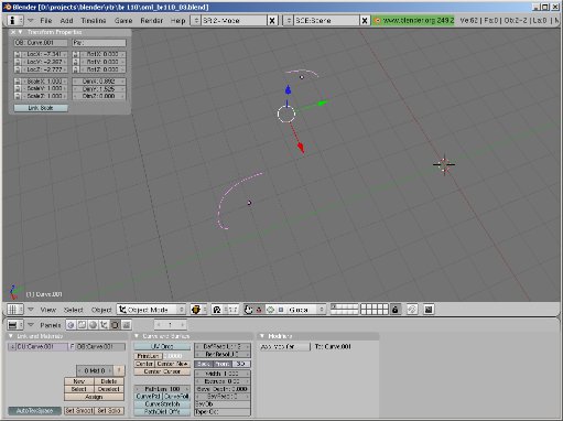
In this section you can use the following procedure. Select the curve and switch with Tab to the Edit Mode. Select the corresponding vertex and display by pressing the n key the global LocX, LocY and LocZ coordinates. Afterwards switch to Object Mode and move the whole object, otherwise the geometry of the curve will be changed.
Rotate the top view curve with rz90. Adjust the vertex with the largest Y-value of this curve to the largest Y-value of the other curve. Then adjust the vertex of the top view curve, which is closest to the Y axis of the scene, to the X value of the other curve (should be 0.000 if everything went ok so far). Now adjust the Z value of the top view curve to the Z value of the other curve which has the largest Y value. o.O (it's quite a long time ago I wrote this tutorial and I hope the translation is properly...)

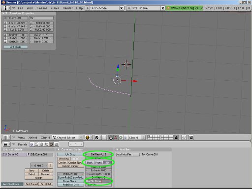
Select the top view curve. DefResolU sets the resolution of the curve. The lower this value is, the more edged will the resulting mesh be. Deactivate Back and Front and activate 3D. Use the same settings for the side view curve. In BevOb of the top view curve enter the name of the side view curve and press Enter.
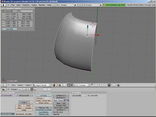
Using DefResolU: 6 this is the result. Alt+c changes the curve to a mesh with 108 faces. Now it's time for adjusting the width and other noticeable things.
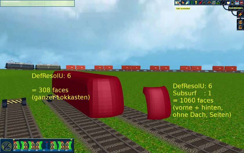
A well rounded mesh uses more resources than an edged mesh. In this tutorial we only made a quarter of the hull.
After mirroring and duplicating it's 4 x 108 = 432 faces. Still missing the bumpers, the bogies, the pantographs,
lamps, roof and details. The bigger one single model is, the less models can be used without restrictions.
Referring to the forums a good value is between 3000-5000 polygons.
The picture shows a comparison within RtR.
last edited: 10. march 2013 © 2010-2013, Olav Müller-Loose